Version 2.7.4
5. 4. 2024This is a small patch release:
- Objects from 3MFs generated by BambuStudio now retain multimaterial painting when loaded
- Fixed a bug where downloading files from Printables did not work when enabled in Preferences
This is a small patch release:
This is the stable release, bringing minor improvements and several bugfixes.
We implemented changes to the printing volume settings and new filament tip routines used by the MMU3 on the MK4.
When using spiral vase mode, the toolpaths are generated as usual and the resulting extrusions are then extruded while gradually increasing z. This approach led to seam-like artifacts on the print in places where the layer transitions would normally be. In addition, the last layer would end abruptly, creating a sharp “edge” where the extrusion ends.
Both these issues were addressed by @andrewboktor by interpolating between adjacent layers and by gradually reducing extrusion flow at the very end of the print. The improvement was recently merged into OrcaSlicer, and we got a pull request with a port to PrusaSlicer. After we evaluated the feature, we decided to merge it because it is well written, well working and very useful.
Thanks to @andrewboktor for the time and effort invested into the issue, and to both @vovodroid and @tg73 for providing a pull request with a port from OrcaSlicer
PrusaSlicer is now able to open 3MF files generated by BambuStudio and load geometry from them. (#10718, PR #10808, thanks to @cmguo). Please note that BambuStudio allows to save a 3MF containing G-code only, which is not supported by PrusaSlicer and loading of such 3MFs will fail.
Metadata of binary G-code have a new item named objects_info, which lists all the objects in the print and their boundary polygons. The same info was added into the comments at the end of ASCII G-codes. This is useful for controlling the Cancel object feature remotely via Prusa Connect.
This is the stable release, bringing minor improvements and several bugfixes.
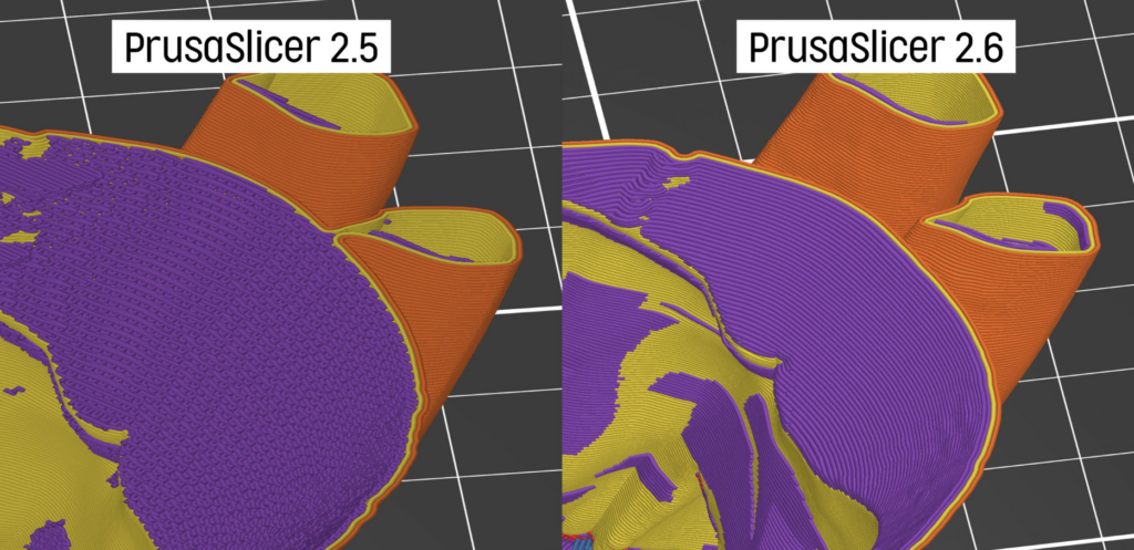
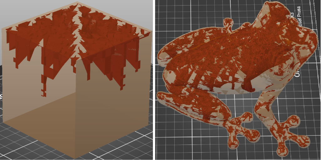
We implemented several mechanisms to detect a non-valid Voronoi diagram, and by manipulating the input, we could ensure that the Voronoi diagram would be valid. We also reimplemented a significant part of multi-material painting from scratch, which, together with the changes above, should resolve all issues with spilled layers for multi-material segmentation.
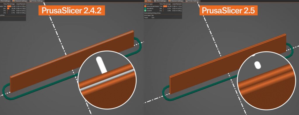
Previously, PrusaSlicer placed the color change (M600) right after the previous layer was finished. The default implementation of color change in pretty much all firmwares returns the nozzle to the exact same position as before the color change started. As a result of this behavior, a small blob of filament with the newly loaded color would get stuck to the print.
Our community, especially @Nohus, came up with a solution of placing the color change after moving to the next layer and position, which proved to be much easier and more universal solution than changing the M600 implementation on the firmware side. Thank you, Nohus, for your implementation and all of you who participated in testing his change.
We’ve replaced helical layer changes introduced in 2.7.1 with a more refined ramping profile. While the helical layer changes helped to reduce stringing, they sometimes caused color blobs and artifacts. With the new and refined ramping profile stringing is still mitigated without the disadvantages of the helical movements.
For SLA printing, we’ve introduced Material Overrides. This new feature, mirroring the flexibility of FDM slicing, allows to override selected configuration options from Print or Printer Settings in Material Settings. There is a new parameter page in Material Settings, which allows to check the parameters which would be overridden and to redefine their value.
PrusaSlicer’s origin is based on the Slic3r project, which was originally written in Pearl scripting language. Over the years, we’ve rewritten nearly all of the code. First the slicing core, then the user interface. We have now rewritten all remaining unit tests still depending on Pearl into C++. Goodbye, Pearl. You will not be missed.
This is the stable release, bringing minor improvements and several bugfixes.
The option Export as binary G-code was removed from Print Settings. Instead, there is a new option in Printer Settings named Supports binary G-code so it can be set at printer level. There is also a new global switch in Preferences->Other, which controls whether binary G-code will be generated for printers which support it. It is now much easier to turn the feature on or off without doing any changes in profiles.
Wipe tower weight was added into G-code metadata so it can be easily displayed in the print statistics on the printer’s display.
Fixed the issue where when ramping travels were enabled, sometimes a perimeter was missing at the layer where the spiral starts.
Fixed a crash when selecting embossed text while an SVG tool is opened.
Fixed a case where helical layer changes could result in out of bed moves.
Fixed a case where helical layer change was enabled even when there was no retraction on layer change.
In addition to the text embossing tool first presented in PrusaSlicer 2.6.0, it is now possible to emboss SVG images onto the models. The feature can be accessed through right button click and it allows similar options for projection and manipulation like the text tool. You can now just drag and drop an SVG logo, title, or even a QR code and merge it with an existing 3D model.
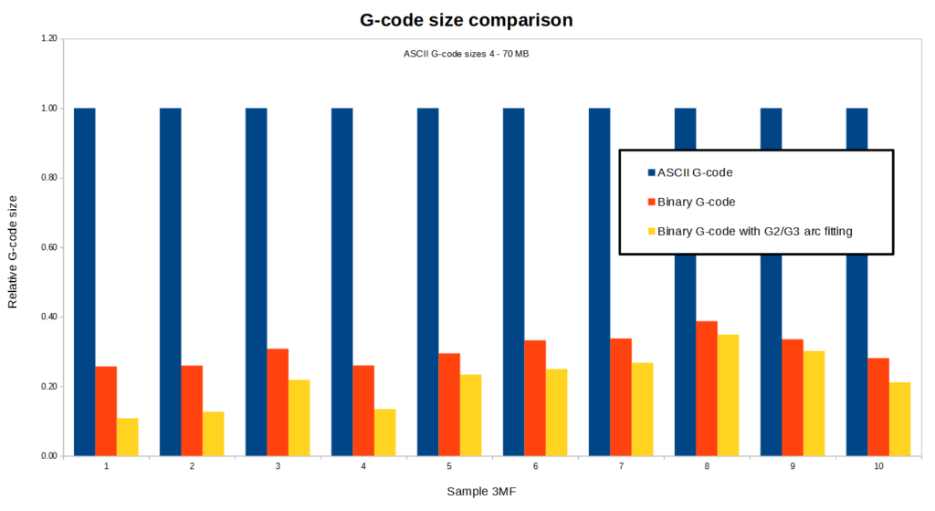
G-code files are easy to read and interpret, but their downside is that the data is not saved efficiently and the file size is often very large. Compression of the file is problematic because the printers usually run on limited hardware and they may not have enough memory and/or CPU power to decompress it. Several solutions to the problem were proposed by members of the community, such as MeatPack encoding (utilizing the fact that the character set of a typical G-code is very limited) or heatshrink compression algorithm (designed to have very small memory requirements).
We are proposing a new standard for a binary G-code format for encoding and compressing ASCII G-code files (see the specification). The format is flexible and the encoding and compression of individual blocks is variable. We also provide libbgcode library which contains the routines to convert ASCII G-codes to binary and vice versa. The library is written in C++ and the repository includes bindings for Python.
Regarding comparison of ASCII vs binary G-code sizes, the result depends on the contents of the G-code. Our testing shows that using binary G-code reduces the size by about 70 % on average. Using arc fitting (described above) at the same time can reduce the size even further. Following chart shows the comparison for 10 randomly selected 3MF projects:
The support for the new .bgcode file format was implemented in PrusaSlicer, including its export, loading configs, previewing G-code or file associations. Exporting binary G-code can be enabled in Print Settings->Output options->Export as binary G-code. An option to convert ASCII G-code to binary (or the opposite) has been added into File menu.
To print a binary G-code, it has to be supported by firmware of the printer. For Original Prusa MINI, MK4 and XL printers, this is supported since version 5.1.0-alpha2. It is necessary to update printer firmware before using the binary G-code format.
We would like to thank Scott Vokes (@atomicobject) for his work on heatshrink and
Scott Mudge (@scottmudge) for developing and maintaining MeatPack.
The Arrange feature has been significantly improved and it is now able to place objects inside concave areas formed by other objects.
Currently there are three distinct levels of geometry handling, which can be selected using a drop-down in the Arrange dialog:
“Balanced” profile produces very similar results to “Accurate” in most cases but it is typically faster by multiple orders of magnitude.
As another improvement, arbitrary bed shapes are now supported.
New cutting mode is now available in the Cut tool. Dovetail mode automatically creates a tongue-and-groove connection that allows sliding one part into the other. The geometry of the connection is adjustable in the Cut tool dialog. Also, a new connector type was added (Snap).
The Emboss tool introduced in 2.6.0 now allows much better projection on curved surfaces. The feature is accessible through a Per glyph orientation checkbox in the the Emboss dialog. When checked, the individual glyphs are (perpendicularly) projected along a curved line on the surface. The idea was inspired by the implementation in BambuStudio.
Organic Supports
In this release, we are presenting our significantly improved implementation of tree supports, which we call ‘Organic supports‘. We choose a new name for our supports because of their distinctly smooth shape and several differences in their behavior. Our implementation is an evolution of the tree supports by Thomas Rahm, which are significantly improved tree supports originally from Cura. We would like to thank Ultimaker Cura and Thomas Rahm for the effort they have invested into the problem.
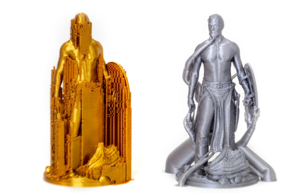
In contrast to the previously common implementation of tree supports, the branching of our Organic supports is smarter and we made them straighter (shorter), smoother, and more stable. The cross-section perpendicular to the branch axis is guaranteed to be circular, and the algorithm automatically uses double perimeter walls for the trees where needed (this is configurable).
The Organic supports are easily removable, do not scar the surface, and are fast and cheap to print. Models can now be printed in orientations that were previously unthinkable (mirroring SLA printing capabilities) and supports for even the most complex shapes are typically easy to remove. Organic supports can be manually enforced or blocked using the Paint-on supports tool.
Automatic FDM Support Painter
PrusaSlicer now has an automatic painting tool for defining areas requiring supports, factoring in various aspects like the model’s center of mass, bed movement, potential extruder collision, material, and bridging. It can also automatically detect if a print requires supports and alert the user in the case they are not enabled.
Text embossing tool
The new Text tool lets you insert, manipulate, and edit text as a 3D object. This provides a convenient way to customize models and add elements such as notes, signs, or serial numbers directly in the slicer.
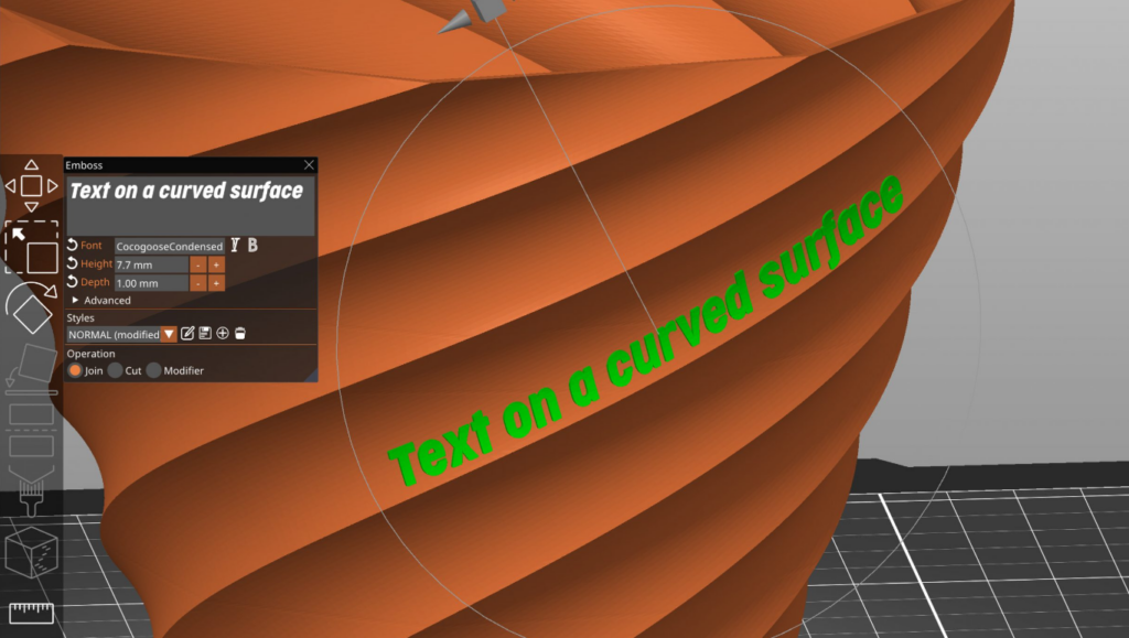
Texts can be embossed, debossed, or even used as a modifier. However, the tool even offers the ability to make the text follow curved surfaces. To change the text position, you can simply drag it on the object’s surface. The text editor automatically imports the font library installed on your device (all TrueType fonts should work).Even after closing the Text tool, the text remains fully editable. The same goes for re-opening 3MF project files. You can also create and save text styles to reuse them in future projects.
Improved Cut tool
The Planar Cut tool has been available in PrusaSlicer for a long time. It is handy for preprocessing huge models that don’t fit the build volume or which are too complicated to print in one piece. With this release, we are extending its functionality.
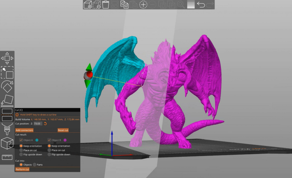
You can newly cut the model at any angle. Defining the precise cutting angle can be done both by a 3D gizmo or by simply drawing a cutting plane by dragging the left mouse button while holding down the Shift key. If the cutting plane intersects the model in several different regions, you can select which parts to cut and which to keep connected by right-clicking on them.
You can select if the cut part should be placed on the bed with the newly created flat surface. You can also choose to keep the alignment of the parts, for example, for printing with a multi-tool printer.
Adding connectors and dowel pins
We understand how important it is to assemble the final parts together with an emphasis on precision and simplicity. That’s why we added an option to define various types of connectors. You can control the depth, size, and tolerances of each connector and the negative hole.
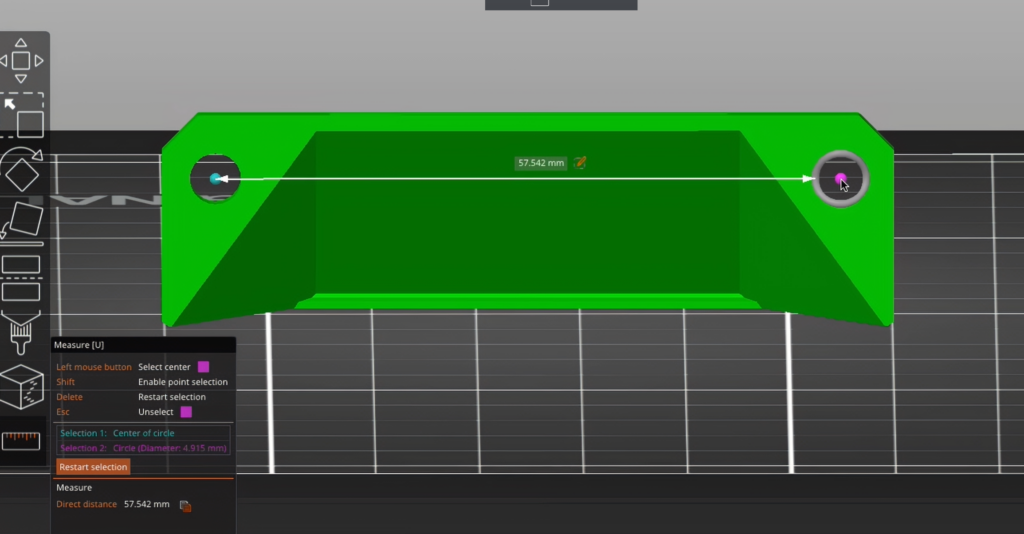
Measurement Tool
PrusaSlicer now includes a measurement tool for gauging distances between vertices, edges, and planes. You can also use it to measure angles, and to scale objects uniformly by editing the measure distance.
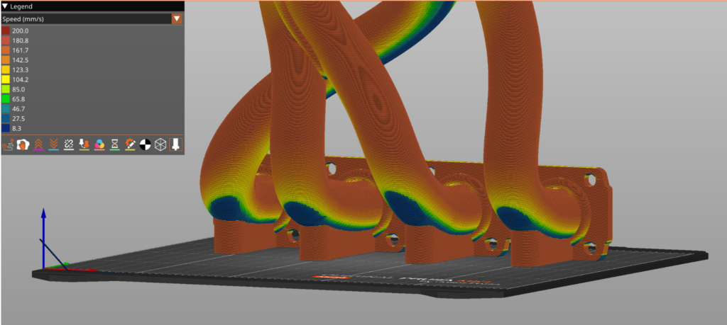
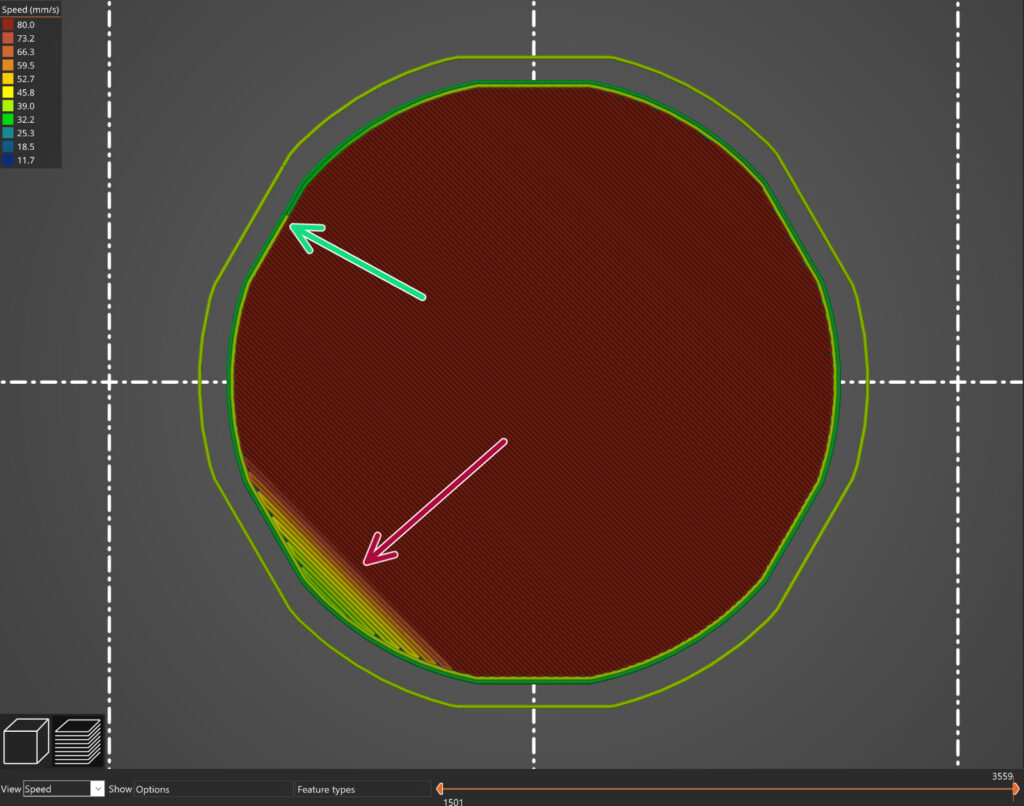
Dynamic overhang speed (and dynamic fan speed on overhangs)
This feature lets you slow down the print speed when printing overhangs, which enables better cooling when it’s needed. The algorithm calculates extrusion overlap with the previous layer and applies speed calculated from the overhang slowdown function. Users can control the shape of the overhang slowdown function via four input points – each point has an extrusion overlap value expressed as a percentage of the full width, and desired speed on such overlap. The speeds in between the control points are calculated via linear interpolation.
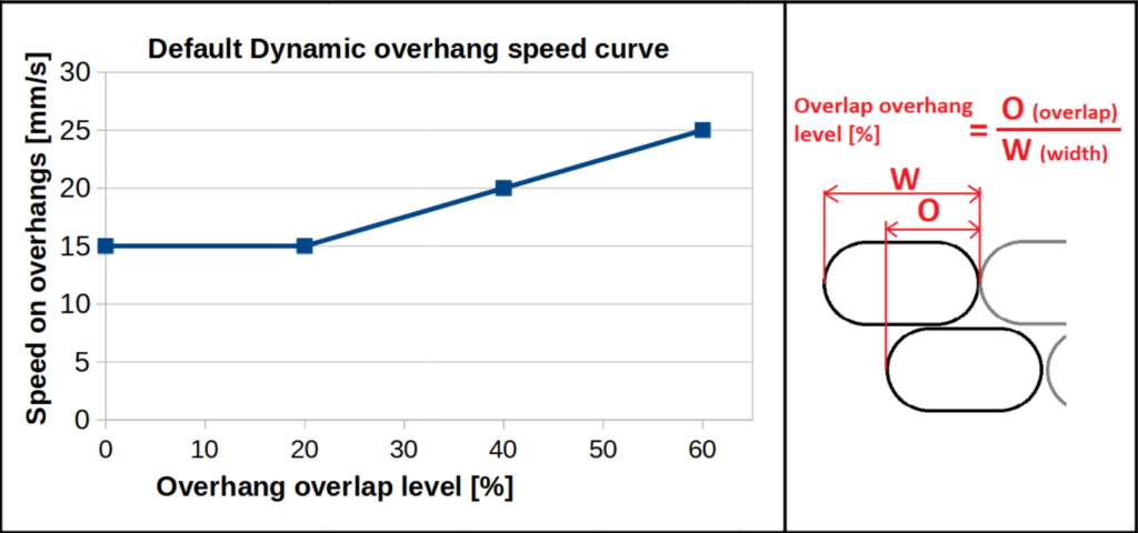
Similarly, users can create custom fan speed curves, so that extreme overhangs get increased cooling. Of course, with some polymers, too much cooling will negatively impact the mechanical properties.
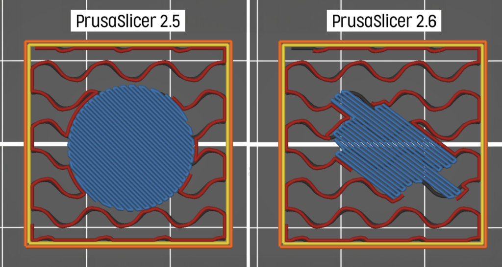
Extending sparse infill
A long-standing issue was connected to bridging solid infill printed over sparse infill. The shape of such infill islands was only determined by what was above, and the infill lines were often inadequately supported as a result, leading to mid-air extrusions and possibly failed prints. PrusaSlicer now extends the lines of the bridge infill so that their ends are supported by the sparse infill on the layer below. The bridge infill is now always using ‘Thick bridges’. The new algorithm works for all infill types. The comparison image below shows exactly the same model (a cube with a counterbored hole in the top face).
Improved Ensure vertical shell thickness
PrusaSlicer 2.6 improves the handling of vertical shell thickness on sloping surfaces. Previous versions used rectilinear infill to address thinning walls and potential holes in steeply sloped areas. The latest version now identifies regions where short rectilinear lines could cause vibrations and surface artifacts, replacing them with a concentric infill. This method often leads to 10-15% shorter print times without compromising quality.
Other new features
New perimeter generator Arachne
For years, the strategy PrusaSlicer used when generating perimeters was to offset the contour of the object with an extrusion line of constant width. This caused issues in various cases, especially when printing thin walls, text, or logos.
The developers of Cura recently implemented a new strategy named Arachne based on the paper [Kuipers et al., 2020]. The Arachne generator produces perimeter loops and gap fills with varying extrusion width. Simply put, it automatically makes perimeters wider or thinner as needed. This is a major change! Before, it was nearly impossible to create a wall that would fit 2 perimeters exactly. And now? As long as the wall thickness is close enough to 2 perimeters, PrusaSlicer will take care of the rest.
The new approach produces nicer-looking prints with fewer artifacts. There is a significant reduction in gap fill, small extrusions used to fill gaps between perimeters, which also results in a reduction of print time.
STEP file format support
Starting with this release, PrusaSlicer is able to import STEP files, which is a format widely used for 3D modelling data exchange. Note that the model is tessellated on import and the slicing algorithms operate on the resulting triangle mesh, i.e., the model is not sliced analytically.
We use Open CASCADE Technology (OCCT) development platform to read the STEP files. It is a CAD kernel also used e.g. by FreeCAD or KiCad. Thanks @Open-Cascade-SAS for keeping it open-source. The import implementation itself was ported from BambuStudio, thanks @bambulab.
Lightning infill
Infill serves a dual purpose – to provide structural rigidity and to support top surfaces. In case structural rigidity is not needed, a lot of material and printing time is saved with the new Lightning infill, which is optimized to support the top surfaces only. The lighting infill generates a branching structure that gets progressively denser towards the top surfaces to support them reliably.
The lighting infill is based on paper [Tricard et al., 2019]. Like the Arachne perimeter generator, we have ported the Lightning infill from Cura, thanks again for keeping Cura open source.
Improved seam placement based on the visibility
Starting with this version, seam placement algorithm prefers regions which are not visible from the outside of the model at all or which are occluded from most directions. The new visibility algorithm is applied for seams set to Nearest or Aligned.
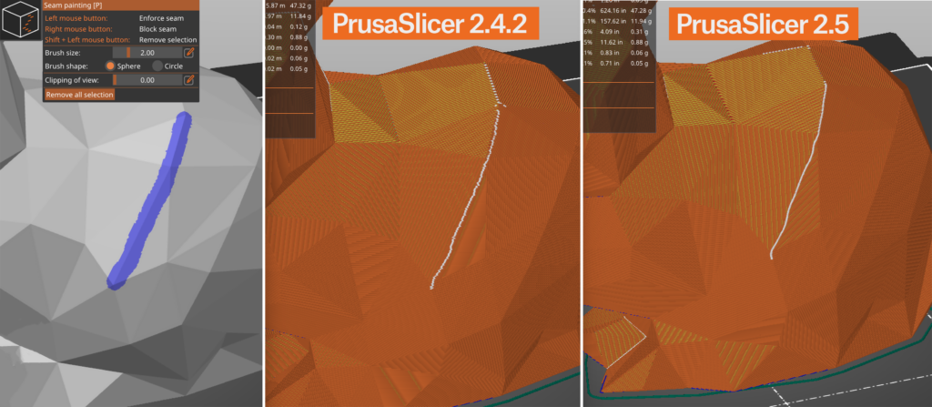
In addition, when paint-on seams are used and ‘Aligned’ is set, the resulting seam line attempts to find a sharp corner in the painted area and snap to it, leading to smoother lines along the sharp edge. Previous versions did not detect the sharp edge in this scenario.
Also the new algorithm strives to produce possibly long and smooth seams on smooth surfaces, while the old algorithm often produced disconnected random bits on such surfaces
Pressure equalizer
An FDM 3D printer consists of a motion system and an extrusion system. While the motion system loves to accelerate and decelerate smoothly to reduce vibrations, the extruder loves to extrude at a constant rate for the best extrusion consistency. That means, unfortunately, that the optimal conditions of the motion system and extruder are in conflict.
Bowden-style extruders are especially sensitive to pressure fluctuations, due to the slack in the Bowden tube, they are not able to reproduce rapid changes in extrusion rate reliably. The Pressure equalizer smooths sudden changes in speed between two features (e.g. between printing infill and perimeters) and reduces print artifacts caused by rapid extruder pressure fluctuations.
Before moving from a faster internal perimeter to a slower external perimeter, the pressure equalizer slows down gradually at the end of the internal perimeter to reach the extrusion rate of the external perimeter. Similarly, when moving from the external perimeter to the infill, the start of the infill is slowed down to the external perimeter speed and accelerated gradually.
New printer and material profiles
Many bugfixes and smaller improvements
Bugs fixed
Localization
Profiles
G-Code substitutions
PrusaSlicer supports processing of the generated G-code with an external post-processor for a long time. Launching an external post-processor is versatile, however it is complex to setup, the post-processing scripts must be distributed with the project and the interpreter running the post-processing script (for example Python) has to be available. We collected many real world use-cases for the post-processing scripts and concluded that many of them could be covered by a simple “Find and Replace” tool with regular expression matching and substitutions.
To make life easier for everyone who only needs basic post-processing, we now integrated such a tool directly into PrusaSlicer. It is accessible from Print Settings -> Output options and allows to add a number of find and replace pairs, with optional regex matching, case sensitivity and whole word matching, similar to what common text editors offer. The G-Code is processed before it is previewed, so your changes will be visible in the G-Code preview.
Other improvements
Bugs fixed
G1 command which appeared before bridging perimeters were printed.To make coloring models for MMU printing quick and easy, we implemented the Smart fill and Bucket fill tools. With the Smart fill tool selected, as you hover the mouse above the model, you get a real-time preview of the automatically detected region to paint. The paint fills a region below the mouse cursor up to a sharp edge, with the threshold angle adjustable. You can also quickly swap continuous patches of color with the Bucket fill tool. Of course, you can also zoom in and use the Brush tool to paint manually. It will automatically split big triangles into smaller ones. During slicing, the painted regions are cleverly extended inwards, giving the different colors/polymers the best chance of binding together.
We introduce a new type of “Snug” supports. These supports maintain the shape of the overhang, so they do not leak to the walls. The trade-off is the possibility of lower stability of tall and thin support pillars. We are leaving the grid supports as the default, for now.
You can now set the support contact distance on the top and bottom independently. If you enable “Support on build plate only”, the support columns will be trimmed to not land on top of the object. The expansion of the first layer is now configurable (very common request). Prints on top of a raft now look better. When you use support enforcers (paint-on or modifier shapes), they will take over “supports on build plate only” and over “don’t support bridges”. You can highlight overhangs when painting supports. Using a new checkbox you can limit the brush strokes only to the highlighted overhanging triangles. Lastly, the “Smart fill” tool is also available when painting supports.
The new default behavior uses your current layer height for bridging, making bridging reliable for shorter distances, but looking significantly better. This is the strategy that most modern slicers use. You can switch to the old behavior by enabling the “Thick bridges” option. Since the first solid layer above supports uses the bridging settings, this change also has a big impact on how supported overhangs look.
The new built-in shape gallery provides a quick and easy way to access your most used models, whether you use them as modifiers or to be placed on the platter and printed. The default shapes include basic primitives (cube, cylinder, sphere…) as well as other useful objects, such as a helper disk or a recycling symbol. You can expand the library with your own models. If you add a model, it will get an automatically generated thumbnail. However, you can replace the generated PNG thumbnail with your own image.
Fuzzy skin lets you create a rough fiber-like texture on the sides of your models by randomly offsetting the perimeter points. It produces surprisingly nice results suitable for tool handles or just to give the print surface a new interesting look. Or to hide print imprecisions. You can also use modifiers to apply fuzzy skin only to a portion of your model.
We have parallelized and optimized the G-Code export. This results in significant improvement of performance. The total slicing time is now 2× to 4× faster, with higher speed up achieved on high-end CPUs with many cores and threads.
PrusaSlicer already supported dark mode on OSX and Linux, based on popular demand, we implemented dark mode for Windows as well.
Brim settings are now object-specific. That means you can turn on brim just for some of the objects, use different brim widths for individual objects, etc. This seemingly small change required a surprisingly significant change of PrusaSlicer’s code. You can now also select to generate outer brim, inner brim, or both.
The negative volume lets you subtract one mesh from another. Similarly how boolean operators work in other 3D programs. That way you can, for example, create easily resizable holes directly in PrusaSlicer. Or you can load one of the objects from the new Shape gallery as the negative volume.
When PrusaSlicer detects the model looks like a logo or a sign, a notification will offer you to automatically add color changes to the correct heights. This feature was proposed by Richard Horne, thank you for the suggestion! It saves you time and removes the guesswork from inserting the color changes at the right height.
We present “Did you know” hints inside a notification, often providing a hyperlink to highlight a user interface element (toolbar button, configuration parameter) or to open the documentation in a web browser. Every time you launch PrusaSlicer, one hint notification is displayed. You can disable them in preferences.
You can now reduce the number of triangles in a mesh using the Simplify mesh feature. Right-click the model and pick Simplify model from the context menu. You can limit the simplification either by detail level or by the ratio of triangles to remove. This feature can also be used to create the “Low-poly effect” directly in PrusaSlicer.
To allow slicing the 3DLabPrint models, PrusaSlicer implements a new “Slicing Mode” option, allowing one to switch between the “Positive” (default) and “Even / Odd” fill rule. Use the “Even / Odd” option to slice 3DLabPrint airplanes correctly. Yet another new “Slicing Mode” option “Close Holes” makes PrusaSlicer fill in all internal structures.
When you upload the G-code via the network, a new progress bar is displayed as a special notification. And the existing “Print Host Upload Queue” dialog newly supports sorting by columns and a file size column has been added.
The clearance areas are now visualized in the scene when moving objects and in case of a collision. This makes it very easy to spot potential collisions.
We newly let the user choose from 3 different auto-orientation algorithms:
You can now easily compare the differences between 2 profiles with a special view. Enable it by selecting Window-Compare presets.
When you drag the horizontal slider in the preview screen, you can inspect the order of moves in the current layer. Newly, we also display the generated G-code on the left side of the screen, including the line number. This can be used for advanced G-code analysis.
In order to focus our future efforts, we decided to optionally collect some general information about the systems PrusaSlicer is commonly executed on. Such system information will help us to deprecate support of obsolete platforms in order to concentrate on up-to-date hardware and operating systems to reduce maintenance cost, improve PrusaSlicer performance and bring up new features. The system configuration data collected are strictly anonymous and you can inspect the full content in the “Send system info” dialog. This prompt is only displayed once. We want to thank in advance everyone who decides to share their system configuration with us.
Based on many requests, we are newly allowing an object to be moved below the print bed to print just the part of the object above the print bed. Arguably this was already doable with the “Cut” tool. But the new way is much simpler to use and very handy, for example, if you just need to flatten the bottom of an uneven object to be printable without a raft. There is also a new button “Drop to bed” at the object manipulation panel to move the object back to the print bed. The intersection of the model with the bed is visualized with a white outline. Moving objects below the print bed is not allowed in SLA mode, for now. It would make the placement of SLA supports confusing.
Summary
SL1S SPEED and CW1S support
Support for Prusa SL1S printer. Files to be printed on Prusa SL1 resp. SL1S printers are exported with an “.sl1” resp. “.sl1s” extension. The firmware updater now supports CW1S.
Prusalink host type
Support for a new PrusaLink host type. PrusaLink is a new name for the networking interface of our printers (SL1/SL1S, MK3 with a PrusaLink Raspberry PI zero image) – you may also know it as Prusa Connect Local. We are also working on PrusaLink for Prusa Mini. The host type of SL1 in PrusaSlicer has been renamed to PrusaLink for clarity.
Smoother surface with Monotonic infill
In PrusaSlicer 2.3.0 we have introduced the Monotonic infill for top/bottom surfaces. We received feedback, that the top surfaces were not always smooth because the monotonic infill was only applied to the topmost infill, but not to the solid infills below. In PrusaSlicer 2.3.2, if the top solid infill is Monotonic, all internal solid infill is newly Monotonic as well.
Installation wizard improvements
When opening the Installation Wizard to install a new printer or a new filament / SLA material, PrusaSlicer newly offers to install configuration updates first before opening the Wizard, because otherwise the user may not be presented with all printers, filaments or SLA materials available.
Support for forward compatibility of configurations
Support for forward compatibility of configurations. Imagine a new infill type is added to a future PrusaSlicer release. If a 3MF was created using the new infill type, PrusaSlicer 2.3.1 would refuse to load the 3MF, while PrusaSlicer 2.3.2 will substitute the unknown infill type with its default and it will present the substitution to the user. The “forward compatibility” feature supports not only adding new enumerated values. For example infill types or firmware flavors) to existing configuration keys, but also turning booleans (on/off) to enumerated values (for example, “draft shield” will change from “enabled/disabled” to “enabled/disabled/limited” in PrusaSlicer 2.4.0.
Bug fixes and other improvements
Summary
Universal OSX builds, Apple Silicon support
Starting with this release, PrusaSlicer supports the new Apple Silicon MacBooks and MacMinis natively, running about 30% faster than emulated x86-64. The new Universal builds contain binaries of both x86-64 and ARM platforms, thus the distributed package is somehow larger than the previous PrusaSlicer.
Chrome OS support
Chromebooks are getting increasingly popular due to their low price, good usability and stability. This makes the Chromebooks the number 1 pick for the US educational institutions. Luckily Google now offers a containerized Linux on modern Chromebooks out of the box and PrusaSlicer runs in the virtualized Linux environment nicely.
Some users managed to run PrusaSlicer on Chrome OS before, see this post.
We have documented installation of PrusaSlicer on Chrome OS in our installation guide.
New 3rd party printer profiles
Vulnerability issues fixed
The Talos Cisco Intelligence Group did a great job identifying potential security issues in loading invalid and potentially malicious AMF and 3MF files, see their vulnerability reports TALOS-2020-1222 and TALOS-2020-1218. We fixed these two potential security issues with this release of PrusaSlicer.
Bugs fixed with respect to PrusaSlicer 2.3.0
The new Paint-on supports tool lets you paint directly on the object and select areas, where supports should be enforced or blocked. You can visualize overhangs and automatically paint the model based on a set overhang angle. Paint-on supports are also saved in the 3MF project file.
Ironing lets you smooth flat top surfaces by running a special second infill phase in the same layer. As the hot nozzle travels over the just printed top layer, it flattens any plastic that might have curled up. The nozzle also extrudes a small amount of filament to fill in any holes in the top surface.
A new default infill pattern for the top and bottom layers. The infill lines are extruded always in the same direction, left to right monotonically. This leads to a homogenous texture without ridges.
Adaptive cubic infill gets automatically more or less dense, depending on the distance to the nearest wall. This results in a shorter print time and lower filament consumption. The Support cubic infill works similarly, but it gets automatically denser depending only on the distance to the nearest top layer.
The legend in the preview now shows a breakdown of print time by feature. You can also click any of the features to hide them in the preview.
The PrusaSlicer G-code Viewer is a lightweight application, which you can use to quickly preview G-codes from all popular slicers. Its behavior is identical to the preview in PrusaSlicer (the same code is used), however, you can load an external G-code file.
The Arrange function is newly customizable. Right-clicking the ‘Arrange’ icon at the top toolbar opens a dialog to tune the distance between objects and to allow rotation of objects around their Z-axis during the arrangement.
If you make any changes to settings and then decide to choose a different print profile, you’ll be offered to transfer your changes to the new profile, discard the changes, save them as a new profile or cancel the operation.
Fill bed with instances feature fills the print bed with the maximum number of copies of a selected object. This feature is accessible from the context menu after right-clicking on an object.
The new search function in the top toolbar allows you to quickly access a particular settings page and parameter field. The search is accessible from both the Plater top toolbar and from the Print/Filament/Printer parameter pages, or with the familiar Ctrl+F shortcut.
Avoid crossing perimeters is an algorithm to minimize crossings of external perimeters during travels, which reduces stringing and improves overall print quality. The new algorithm is much more accurate and significantly faster.
PrusaSlicer separates the physical printer connection settings from the Printer profile into new Physical Printer profiles.
Thanks to the community submissions, PrusaSlicer now has more built-in profiles for Anycubic, Creality, Trilab, and Lulzbot machines.
It is newly possible to import both a model and its print profile from an existing .SL1 archive. Note that the original model is not available in the SL1 archive, it has to be reconstructed from the slices. The imported mesh will be visibly discretized and the supports (if they were used) will be fused with the object.
Mini supports are now generated in regions where the normal supports would not fit.
You can now choose to display settings in a non-modal window (Configuration-Preferences-GUI). This is especially useful in a multi-monitor setup.
The sidebar can be hidden with a button or by pressing the Shift+Tab shortcut. This is especially useful when working on a smaller laptop screen.
The new notification system replaces some of the old pop-up windows and informs the user about possible warnings, errors or actions (eject removable media).
Modifiers and custom settings can now be copied and pasted to another object in the object list.
Anchoring of sparse infill to an inner-most perimeter has been reworked to never overlap anchor lines over each other. The length of the sparse infill anchors can be configured with the new “infill_anchor” parameter.
PrusaSlicer now starts significantly faster and has a splash screen.
More info at full Github changelogs: 2.3.0-rc2, 2.3.0-rc1, 2.3.0-beta3, 2.3.0-beta2, 2.3.0-beta1, 2.3.0-alpha4, 2.3.0-alpha3, 2.3.0-alpha2 and 2.3.0-alpha1.
In the SLA mode, we’ve added hollowing with drainage hole generation. Hollowing a model is a great way to reduce resin consumption and internal stress in bigger models.
We’ll be working with you, the community to select and manage profiles for each vendor.
When printing the first layer is squished against the heated print bed and as a result, it’s usually a bit wider than it should be. The elephant foot compensation is a handy feature, which prevents this from happening, by shrinking the first layer a bit. However, previous PrusaSlicer versions would also shrink thin lines, which was a problem. The new adaptive version now properly respects thin lines but shrinks everything else by the set value. Official Prusa profiles will have this feature turned on by default from now on.
The variable layer height can now be calculated automatically, but you can still adjust the height curve manually.
If you insert an SD card or USB flash drive a dedicated button for Saving G-codes to removable media will automatically appear. And the eject button is here too.
Saved 3MF project files now have handy thumbnails, which are by the way supported by prusaprinters.org.
Filament profiles filtering has been added to the configuration wizard.
The path planning has been improved and now produces fewer travel moves.
The Reload from disk function now works even in re-opened 3MF files. This feature is great for cases, where you created a newer version of your model and you want to replace the old version in PrusaSlicer without having to set up things like custom supports or modifier meshes all over again.
A feature that was heavily requested by the community is inserting a pause at a certain height. That can be used to insert magnets, weights or nuts into your prints. And you’ll get time estimates till each pause. And in a similar way, you can now insert a custom G-code at a certain height. That’s useful for advanced users when creating calibration G-codes like a temperature tower.
When adding a Color change you can now pick the color and get an accurate preview.
We’ve added Color Print for the MMU. This is rather complex, but a simple use-case is replacing manual color change with an automatic swap done by the MMU. Speaking of the MMU, we added the option to make the wipe tower without sparse layers. Which reduces wasted filament and often the print time as well.
You can now set a top and bottom minimum wall thickness, which is especially useful when using the variable layer height function.
Sequential printing now follows the order of models in the object list. You can change the order simply by drag and dropping. Plus by pressing the E key you can see the object number and name in the 3D view.
Undo/Redo
All the actions accessible from the Plater are now undoable including object selection, actions at the side bar (adding modifiers, changing their attributes). We believe we have the best Undo / Redo implementation in the world of FFF and SLA desktop printing software. 😉
Height range modifiers
Just like modifier meshes, they let you change settings for a specific part of the model. However, modifier meshes are geometry-based (e.g. a cylinder-shaped area defines where supports shouldn’t be created – support blocker), while height range modifiers are based on, surprise, height information. So you can easily set different infill density for the base of the model and for the rest of the model. Height range modifiers can be used in a variety of ways, including changing the layer height for various parts of the model.
SLA pad around object
Starting with PrusaSlicer 2.1, it is now possible to place the object directly onto the printing platform and generate supports wherever necessary or even add a pad around the object.
Perspective camera
You can now switch between orthographic camera (old default) and perspective camera (new default). The perspective camera represents our view of the world more faithfully (objects farther away from the camera are smaller). Maybe you will start switching the cameras on the fly, because each of them has its advantages.
Toolpath export as OBJ
FDM tool paths can now be exported into an OBJ file to be rendered by a photo realistic renderer. The initial idea and code was provided by Paul Arden, see his wonderful renders on twitter. The tool paths could be exported after the G-code is generated by menu File->Export->Export Tool Paths
Custom print bed models
PrusaSlicer now supports custom print bed textures and models #1875 #2169 #2496. Both PNG and SVG formats are supported for the print bed texture. The image and model files are assigned to the Printer profile from the “Bed Shape” dialog, and the full path to these files is stored into “bed_custom_texture” and “bed_custom_model” Print profile variables.
Other improvements